Maintenance
The Impressor is a precision mechanical instrument and should always be handled with care. The deflection indicator built-in to the Impressor has a normal reading of zero when not in use.
The Indenter Point has a tip precisely-machined to very small dimensions. It should be used with care to prevent damage. Avoid sliding or scraping the Indenter Point when it is in contact with the surface being tested. If the Indenter Point is damaged, it must be replaced with a new one. The Impressor ships with two spare Indenter Points.
WARNING
Do not attempt to regrind an Indenter Point when damaged! The mechanical dimensions of the Indenter Point determine the accuracy of readings and will create erroneous reading when reground.
To check the condition of the indenter point, first visually inspect it for damage. Then place the impressor on a hard, flat surface with the appropriate test disk positioned under the indenter point. Press the impressor handle down firmly, but carefully, to avoid sideways slippage of the indenter point. The reading on the indicator should be within the range of values stamped on the test disk. If it is not, refer to the calibration procedure below.
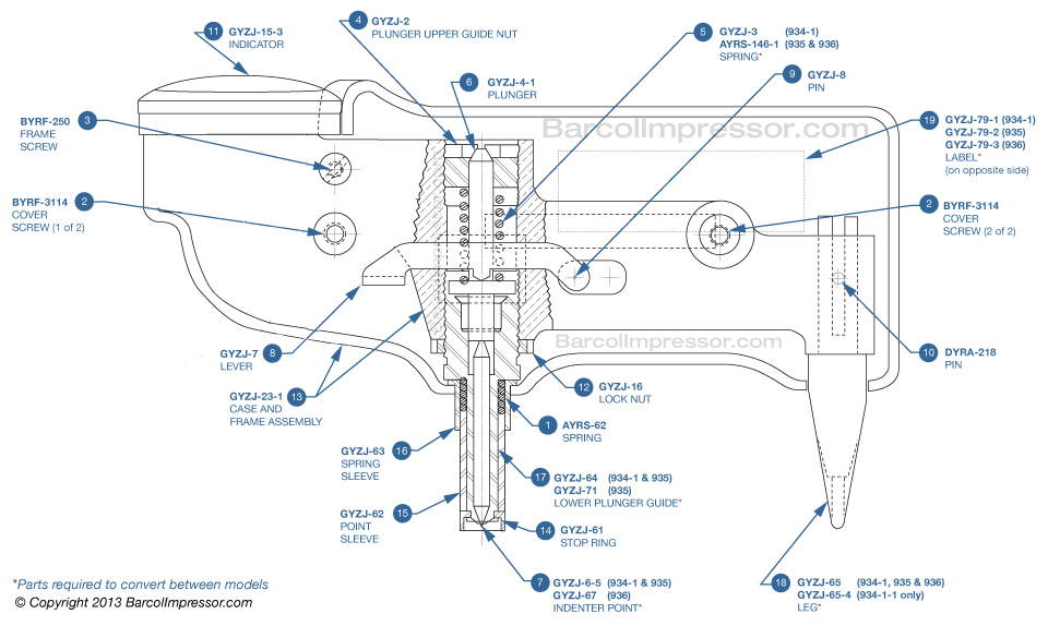
Replacing the Indenter Point
- Clean the new indenter with alcohol.
- Remove the two screws that hold the impressor case halves together (see Figure 1).
- Lift out the frame while holding the spring sleeve in place (so it will not fall off) until it can be removed.
- Loosen the plunger upper guide nut with the provided wrench until the crossnotched top lip protrudes above the frame.
- Hold the impressor upside down (so the spring and plunger won?t fall out), then loosen the locknut with the provided wrench and remove the lower plunger guide.
- Replace the indenter point in the lower plunger guide, then re-install the lower plunger guide, leaving about 3/16 of an inch of thread protruding below the frame.
- Tighten the lock nut, then operate the Impressor against a moderately hard surface 20 to 30 times in order to properly seat the indenter.
- Tighten the plunger upper guide nut until its top is flush with the frame.
- Calibrate the impressor per the procedure below.
- Replace the spring sleeve, reassemble the case halves and screws, and test for the appropriate reading on the test disks.
Calibration For the GYZJ-934-1
- Set the top adjustment nut about 1/16" below the top of the frame.
- Calibrate against the 87/89 disk using the bottom adjustment nut.
- Calibrate against the 43-48 disk using the top adjustment net.
- Repeat steps 2 and 3 until both readings are within specifications.
Calibration For the GYZJ-935 and GYZJ-936
- Set the top adjustment nut about even with the top of the frame.
- Calibrate against the test disk using the bottom adjustment nut.